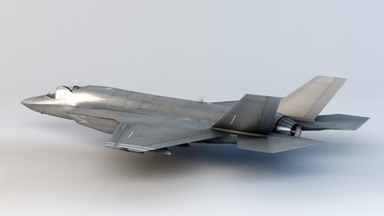

Modern day aircraft are equipped with various types of antennas that are vital not just for flight safety but also for navigation. For example, a typical Boeing 787 is equipped with 21 different types of antennas on its body which all operate in different bands. Similarly, a typical F-16 fighter aircraft is also equipped with 8 to 10 different antennas, ranging from omnidirectional to conformal, on its body. When structural designers design aircraft, they tend to assume a plain airfoil shape of both the wing and fuselage because of which their design is optimized for that kind of shape. Since these antennas eventually become essential part and parcel of aircraft body, they tend to increase the aerodynamic drag. Moreover, when these antennas are placed into the curving skin of aircraft, their location must be chosen carefully so that there is no cross-interference due to their operating frequency and band. Consequently, the location of these antennas has to be optimized not just to eliminate interference but also to minimize the aerodynamic drag. Furthermore, antennas must be developed to cope with environmental phenomena such as static charge build-up, lightning, erosion, and water ingress. Aside from all these requirements, installation needs to be kept as simple as possible so that maintenance is easy.
For a long time, aircraft antenna designers have been grappled with the challenges associated with designing, integrating, and determining the best location to install antennas on an aircraft. The build and test approach can address some of these challenges. However, for a vehicle like an aircraft, organizations are bound to incur huge expenses when they follow this approach. This method requires chambers that are sometimes as large as aircraft hangars, scheduling vehicle assets and their equipment and significant manpower as well as considerations in terms of infrastructure and facilities. Each of these requirements can be prohibitively expensive, potentially limiting the scope of the testing available within a given project.
A team of national and international researchers, headed by Head of Avionics Engineering Department of College of Aeronautical Engineering (CAE), Dr. Azhar Hasan, recently carried out a research study on this topic, i.e. to find out the best location to mount the antenna on aircraft so that both factors, i.e. electromagnetic interference and aerodynamic drag, could be reduced
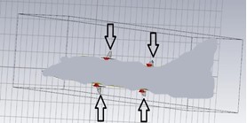
(Figure 1).
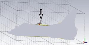
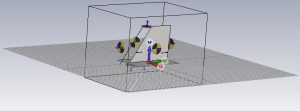
In their work, they focused on co-site interference analysis and antenna location qualification on a fighter jet aircraft. Two blade antennas operating within the frequency range of 0.960 GHz to 1.220 GHz and 0.400 GHz to 0.500 GHz were designed to minimize co-site interference. Blade antenna was chosen because it provides the versatility of communication in VHF, UHF, and microwave bands of airborne communication along-side aerospace friendly properties like low drag and light weight material. The aerodynamic drag force of the blade antenna is reduced by the antenna’s tapered shape while the aircraft is airborne. ‘CST Microwave Studio’ was used to simulate the designed antennas in an isolated environment as well as by mounting the antennas onto an aircraft CAD model (as shown in Figure 2).
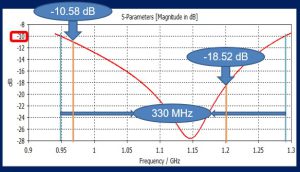
The same simulation platform was also used to find the reflection co-efficient, shown in Figure 3, along with far-field gain pattern within the frequency band.
The antennas were then mounted onto an aircraft CAD model and the radiation pattern was analyzed. The radiation pattern and return loss of the designed antennas were measured. The mutual coupling between the antennas mounted on the aircraft was also measured and the coupling matrix was optimized. Optimum position keeping in mind the gain, radiation pattern, and the co-site interference for an antenna system was found on fighter jet aircraft such that it can provide communication for airborne radio link control at different frequencies.
Their research work, titled “Antenna Installation and Location Qualification Using Computational Electromagnetics Tools” (https://bit.ly/3Gt2yPw) was recently published at IEEE International Congress on Advanced Technology and Engineering held in Yemen and was awarded the Best Paper Award.
The author is Head of Avionics Engineering Department, at College of Aeronautical Engineering (CAE), National University of Sciences and Technology (NUST). He can be reached at [email protected].
Researcher’s Profile: https://scholar.google.com/citations?user=ZuXhwvgAAAAJ&hl=en