 Background. Let’s imagine a scenario to characterize a flashlight. In other words, we are required to develop a diagram describing radiation characteristics of flashlight. We would be interested in measuring the direction and amount of light traveling from flashlight to the surrounding. Investigating the flashlight in a dark room will be a wise choice and our eyes can act as sensor for primary investigation. Now extend the scenario to antennas. Antenna also radiate energy as flashlight do. Antenna radiates RF waves invisible to human eye. Intuition suggest we would require a room behaving dark to these EM waves and we would require eyes visible to EM waves. These special dark rooms build for measuring and characterizing antenna are called anechoic chamber.
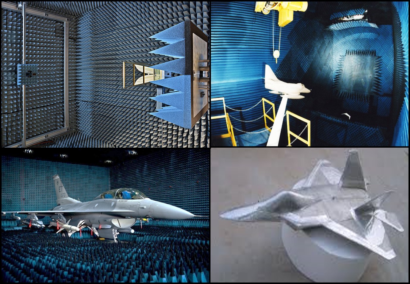
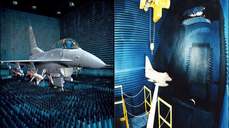
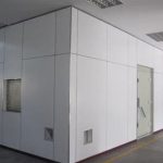
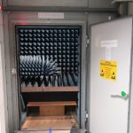
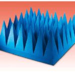
Anechoic Chamber. An anechoic chamber is a shielded room that do not let RF energy to either enter or escape the premises of room. This room incorporate several radio absorptive materials (RAM) of various size and shapes mounted on the inner walls of the room. The entry is managed with a shielding door so that an engineer can mount the antenna inside the chamber and start characterization process remotely from a control room located adjacent to the chamber room. Anechoic chamber is an effective tool required for carrying out effective research in RF & MW domain, specifically the antenna design.
Envisioning the need of quality antenna characterizing facility CAE has planned to induct and commission a multipurpose anechoic chamber that will incorporate Near-field testing (NFT) and Radar Cross Section (RCS) measurement features. The antenna and RCS measurement sub systems will be installed in a single microwave anechoic chamber. The anechoic chamber environment provides a “quiet zone” environment for the measurement system, and other auxiliary systems are configured to ensure the normal operation of the anechoic chamber.
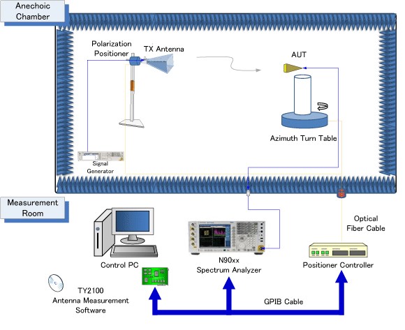
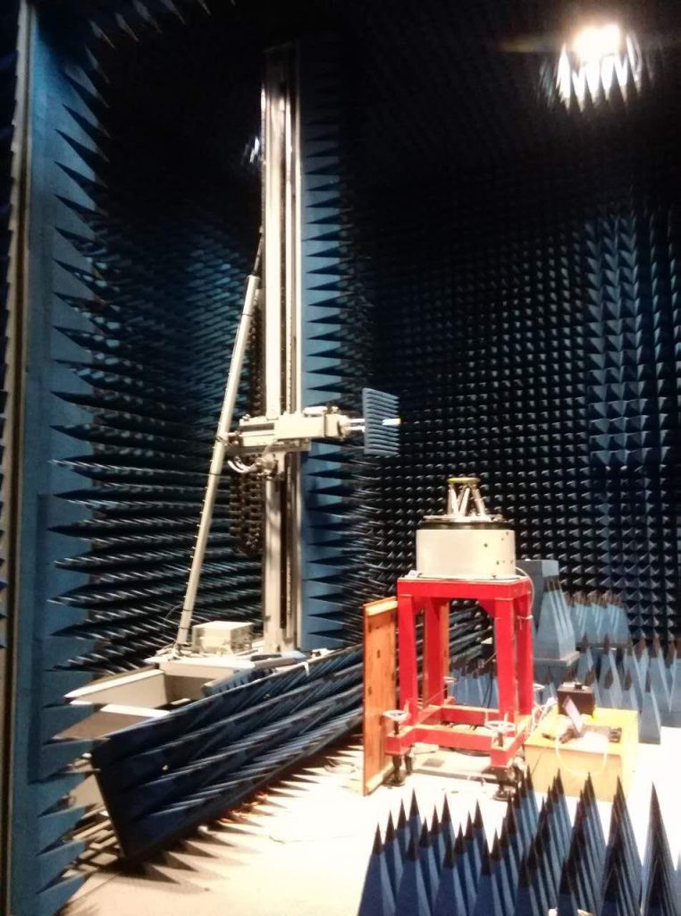
NFT System. In the targeted design scheme, the standard planar near-field scanning frame system has been selected, and the corresponding RF equipment, source / measurement instruments and accessories will be used as the main platform of the system configuration, to realize the planar near-field measurement and data processing. The conceptual working principle of NFT system is depicted in below diagram, where the Antenna Under Test (AUT) will be mounted at one end and NFT scanner will be installed at the other end. The measurements will be performed through NFT software and VNA will utilized as the signal transceiver.
RCS Facility. The main function of the RCS scattering measuring instrument system is to test the radar scattering parameters of various types of targets, and to evaluate the near and far field radar scattering performance. RCS scattering measurement subsystem will utilize same two-dimensional planar scanning frame system as the transmitter as well as the receiver , the vector network analyzer, and the transceiver subsystem. The core instrument of the scattering measuring instrument system is the vector network analyzer. The vector network analyzer will be acting as a transmitter signal source as well as a high-performance receiver. The test facility will also be equipped with a multifunction control room for the installation of remote-control equipment and other terminals such as high-performance workstation and monitoring / voice devices. The commissioned facility will provide CAE a capability to carry out quality research in RF & MW domain under sponsored projects and MS/ PhD thesis.
The author is from Avionics Engineering Department, College of Aeronautical Engineering (CAE), NUST, He can be reached at [email protected].